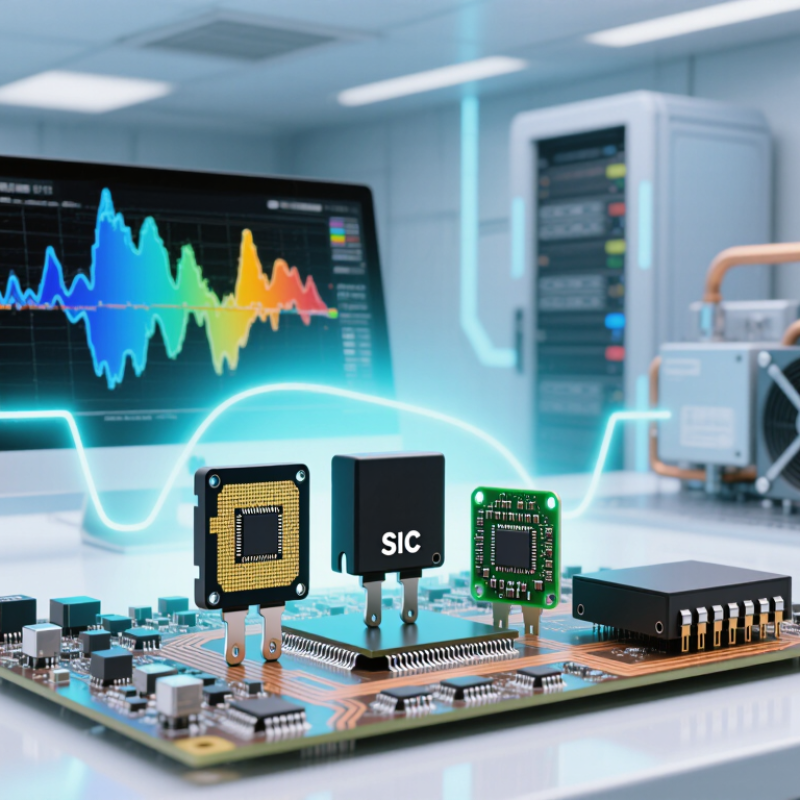
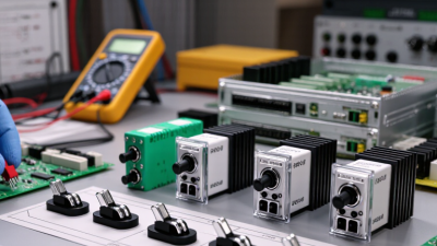
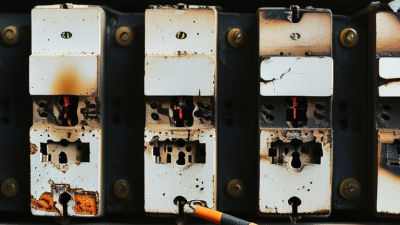
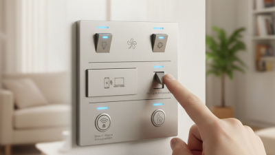
Choosing the right Power Switch in 2026 requires more than comparing purchase prices. Modern converters, motor drives, battery systems, and data-center supplies demand lower losses, faster switching, and stronger thermal control. The International Energy Agency’s Electricity 2024 report projects global electricity demand to grow by an average 3.4% annually from 2024 to 2026. Meanwhile, the IEA’s Renewables 2024 report records about 510 GW of renewable capacity added in 2023. These trends increase pressure on every switching stage.
As Infineon CEO Jochen Hanebeck has stated, “Semiconductors are the key enablers of decarbonization and digitalization.” His point matters at board level and on the workbench. Engineers must examine voltage margin, continuous and pulsed current, RDS(on), gate charge, switching frequency, thermal resistance, and package limits. A MOSFET may look efficient at 25°C, then overheat inside a sealed enclosure. A SiC device may switch faster, yet increase electromagnetic interference and gate-drive complexity. GaN can reduce losses, but layout errors become less forgiving.
The correct choice begins with the real load profile, not a catalog headline. Measure startup surges, duty cycles, ambient temperature, and cooling airflow. Compare conduction and switching losses under actual conditions. Check supplier qualification, lifecycle data, and application support. No selection is perfect. Simulation can mislead. Laboratory testing still matters. A practical design may accept slightly higher losses to gain stability, availability, and easier manufacturing. This guide examines those trade-offs and explains how to select a dependable Power Switch for 2026 applications.
How to Choose the Right Power Switch in 2026?
Define the Load, Voltage, Current, and Switching Requirements
Choosing a power switch starts with the load, not the catalog number. Identify whether it drives a motor, heater, lamp, relay, or electronic circuit. Each load behaves differently during startup. A small motor may briefly demand five times its running current. That surge can damage an undersized switch. Measure it if possible. Estimates often fail.
Check the highest supply voltage, including spikes from long cables or inductive loads. The switch should tolerate more than the normal rail voltage. Do not rely only on typical values. Compare continuous current, peak current, switching frequency, and duty cycle. Heat matters too. A switch carrying 8 A in a warm enclosure may need cooling or a lower resistance rating. In practice, engineers sometimes focus too heavily on current and overlook voltage transients. I have made that mistake.
Tips: Record startup current with an oscilloscope and a suitable current probe. Test the real load, not only a resistor. Confirm off-state leakage, turn-on time, and control-level compatibility. Leave practical design margin, but avoid excessive oversizing because it can increase cost, capacitance, or switching losses. Review the datasheet’s test conditions carefully. They may not match your enclosure, airflow, or wiring. A short bench test is useful, but temperature testing is better.
How to Choose the Right Power Switch in 2026?
Mechanical, solid-state, and smart power switches solve different problems. Mechanical switches remain attractive for simple isolation because their off-state leakage is nearly zero. They also tolerate short overloads well. However, contacts wear, arc, and produce audible clicks. Solid-state switches respond faster and contain no moving contacts. They suit frequent cycling, silent equipment, and vibration-prone cabinets. Their weaknesses include heat, off-state leakage, and failure modes that can be harder to see. A heat sink may become necessary above modest current levels.
Smart switches add current sensing, fault reporting, and remote control. These features matter as electrical systems become more connected. The International Energy Agency’s Electricity 2024 report projects data-center electricity demand could exceed 1,000 TWh by 2026. That growth increases pressure to monitor every avoidable watt. Smart switching can identify overloads before a cable feels hot. It can also record abnormal startup currents, helping maintenance teams find intermittent faults. Yet intelligence is not automatically better. Software, network security, and configuration errors create new failure points. I have seen teams choose smart control when a basic mechanical disconnect would have been safer and cheaper. That decision deserves review. Choose mechanical technology for isolation, solid-state technology for speed, and smart technology when measurable operating data justifies the added complexity. Verify thermal performance under real enclosure conditions, not only catalog ratings. Sources: International Energy Agency, Electricity 2024; IEC 60947-1, Low-voltage switchgear and controlgear.
| Evaluation Dimension | Mechanical Power Switch | Solid-State Power Switch | Smart Power Switch | Selection Guidance |
|---|---|---|---|---|
| Switching Principle | Physical contacts open or close an electrical circuit. | Semiconductor devices switch current without moving contacts. | A semiconductor power switch combined with control logic, sensing, and protection functions. | Choose the architecture that matches the required control, protection, and lifetime level. |
| Typical Voltage Capability | Available from low-voltage circuits to high-voltage switching systems, depending on contact spacing and insulation design. | Commonly used from low-voltage DC systems to industrial AC or DC applications; the practical range depends on the semiconductor topology. | Most commonly used in low-voltage DC power distribution, often in automotive, industrial, and embedded systems. | Verify continuous voltage, transient voltage, isolation rating, and creepage or clearance requirements. |
| Typical Current Capability | From signal-level loads to hundreds of amperes in appropriately rated contactors or breakers. | From milliamperes to hundreds of amperes, with current limited by conduction loss and thermal management. | Commonly handles approximately 1–50 A per channel; higher-current designs require substantial thermal design. | Size for continuous current, inrush current, overload duration, ambient temperature, and cooling conditions. |
| Switching Speed | Typically milliseconds to tens of milliseconds, depending on the mechanism and actuation method. | Typically microseconds to milliseconds, depending on the device and gate-drive circuit. | Usually microseconds to milliseconds, with configurable slew-rate or soft-start functions in some designs. | Use solid-state technology when fast PWM, current limiting, or precise timing is required. |
| On-State Loss | Very low contact resistance when new; losses increase as contacts wear, oxidize, or become contaminated. | Has voltage drop or on-resistance, producing heat approximately equal to current squared multiplied by resistance. | Has semiconductor conduction loss plus control and sensing losses; thermal behavior must be evaluated carefully. | For high-current continuous loads, compare total heat dissipation rather than voltage rating alone. |
| Off-State Leakage | Very low leakage when contacts are open; insulation leakage still depends on the device and environment. | Non-zero leakage current is present and may increase with temperature and applied voltage. | Non-zero leakage is present, along with quiescent current from the control and diagnostic circuitry. | For safety disconnects or ultra-low-power loads, check the maximum specified leakage current. |
| Electrical Isolation | Provides galvanic isolation when contacts are open, subject to insulation and spacing ratings. | Usually does not provide galvanic isolation unless an isolated device or isolated gate-drive arrangement is used. | Normally shares a common electrical domain unless additional isolation circuitry is included. | Use a mechanical contactor or an explicitly isolated solid-state design when isolation is mandatory. |
| Inrush-Current Handling | Can tolerate high short-duration inrush when contacts, wiring, and arc-control design are correctly rated. | May require current limiting, soft start, thermal margin, or a bypass path to manage inrush. | Often supports controlled turn-on, current limiting, and overload shutdown, depending on the design. | Measure the load profile; do not size only from the steady-state current. |
| Protection Functions | Protection is usually external, such as a fuse, circuit breaker, thermal protector, or overload relay. | Basic devices may provide little protection; dedicated versions can include current limiting or thermal shutdown. | Common functions include overcurrent, short-circuit, overtemperature, undervoltage, and reverse-polarity protection. | Select smart switching when integrated fault protection can reduce external circuitry and system risk. |
| Diagnostics and Monitoring | Normally limited to auxiliary contacts, position indicators, or external sensing. | Basic devices provide little diagnostic information; external sensors can add monitoring. | Can report load current, open-load faults, short circuits, thermal status, and switch condition. | Use smart switching for predictive maintenance, remote diagnostics, and fault logging. |
| Acoustic Noise and EMI | May create audible clicking and contact arcing; generally produces little high-frequency switching EMI. | Silent operation, but fast voltage and current transitions can increase electromagnetic interference. | Silent operation with potentially greater EMI-management requirements because of fast controlled switching. | For quiet equipment choose solid-state; for sensitive electronics, validate layout, filtering, and switching edges. |
| Service Life | Limited by contact wear, arcing, mechanical fatigue, and switching frequency; resistive-load life is usually longer than inductive-load life. | No mechanical wear; service life is mainly affected by thermal cycling, electrical overstress, and semiconductor aging. | No moving contacts; reliability depends on semiconductor temperature, protection events, control circuitry, and thermal cycling. | Choose solid-state solutions for frequent switching, provided thermal stress is controlled. |
| Control Interface | Manual, coil-driven, or relay-driven control; generally simple to integrate. | Logic-level, gate-drive, or analog control depending on the semiconductor design. | Logic input with optional analog current-sense, fault output, serial communication, or networked control. | Match the interface to the system controller, isolation strategy, and software requirements. |
| Energy Consumption While On | Contact power loss is low, but a continuously energized coil may consume additional power. | Power loss is determined mainly by on-resistance or forward voltage and load current. | Includes semiconductor conduction loss and the operating current of sensing and control circuits. | Compare both load-side dissipation and control-side power consumption. |
| Best-Fit Applications | Galvanic disconnects, high-voltage isolation, simple power routing, motor contactors, and low-frequency switching. | High-frequency switching, silent equipment, PWM control, battery systems, and applications requiring long switching life. | Intelligent power distribution, embedded systems, automotive loads, industrial controllers, and connected equipment. | Base the decision on load behavior, safety requirements, monitoring needs, and total system cost. |
| Main Advantages | Low off-state leakage, physical isolation, broad load compatibility, and straightforward fault behavior. | Fast response, silent operation, high switching endurance, and compact implementation. | Integrated protection, diagnostics, controllability, fault reporting, and potential reduction in external components. | Prioritize the feature set that directly improves system reliability or operating efficiency. |
| Main Limitations | Mechanical wear, contact bounce, audible noise, arcing, and slower switching. | Leakage current, heat generation, possible failure-short behavior, and a need for careful EMI and thermal design. | Higher design complexity, software or communication dependencies, heat dissipation, and non-zero standby current. | Evaluate failure mode, thermal limits, cybersecurity needs, and service strategy before final selection. |
| Overall Choice for 2026 | Best when physical isolation, very low leakage, simplicity, or high-current disconnect capability is the priority. | Best when fast, silent, high-frequency, or high-cycle switching is required. | Best when protection, diagnostics, remote control, and data-driven maintenance justify added complexity. | There is no universal winner; select according to voltage, current, isolation, switching frequency, thermal limits, and monitoring requirements. |
Note: Ratings and performance vary by circuit topology, load type, temperature, protection design, and applicable safety standards. Always verify the latest electrical and thermal specifications for the selected device.
How to Choose the Right Power Switch in 2026?
A power switch should fit the real electrical environment, not just the nominal load. Check its voltage and current ratings under maximum temperature. Confirm insulation, creepage, clearance, and fault-current ratings. A switch rated for 24 volts may fail during a motor startup surge. Read test conditions carefully. They often reveal the gap between laboratory figures and field performance.
Protection features deserve practical attention. Look for short-circuit protection, current limiting, overtemperature shutdown, reverse-polarity protection, and controlled startup. These functions reduce damage when wiring, loads, or users behave unpredictably. Verify whether protection latches off or resets automatically. That small detail affects maintenance and safety. Use recognized safety standards and request credible test documentation. Do not rely on a single marketing table.
Thermal performance is equally important. Conduction loss rises with resistance and load current. Switching loss grows with frequency and transition speed. Check the thermal resistance from junction to case and board. Then assess copper area, airflow, enclosure temperature, and nearby heat sources. Measure temperature during startup and continuous operation. A brief bench test can mislead. I have seen a cool prototype become dangerously hot inside a sealed enclosure. My own selection process is not perfect, either. I sometimes underestimate connector heating and installation errors. Leave a sensible derating margin, document the assumptions, and review them after real-world testing.
Compare representative power-switch technologies by current capability, maximum ambient temperature, and thermal resistance. Use these values as an engineering reference, then confirm the exact safety approvals, IP rating, insulation requirements, load type, and derating curve in the product datasheet.
The figures are representative reference points for commonly specified low-voltage power-switch classes, not universal limits. Safety selection should also verify IEC 61058-1 or applicable UL requirements, IEC 60529 IP protection, dielectric withstand, creepage, clearance, and overload performance.
Choosing a power switch starts with the control method, not the catalog price. A low-side MOSFET suits simple GPIO control and compact DC loads. High-side switching needs charge-pump or isolated gate-drive support. PWM applications demand low gate charge, fast switching, and controlled electromagnetic emissions. For safety-critical equipment, verify fault behavior and isolation requirements against applicable IEC standards.
Tiny detail. It can change the whole design.
Package selection must match installation constraints. A SOT-23 package saves board space, but it sheds limited heat. A QFN reduces electrical loop area, yet its thermal pad needs careful PCB assembly.
DPAK and TO-220 packages simplify probing and heatsink attachment, though they consume more board area.
The WSTS Spring 2025 forecast estimated global semiconductor sales near 700 billion dollars, showing the market’s scale, not that every switch is suitable. The IEA Electricity 2024 report also projects continued electricity-demand growth through 2026, increasing pressure for efficient power conversion.
In field work, I check ambient temperature, copper area, airflow, connector spacing, and service access before choosing voltage ratings.
I still over-specify switches sometimes. That adds cost and can worsen switching behavior.
Validate the real load, startup surge, enclosure temperature, and installation torque with measured tests, not assumptions.
Choosing a power switch starts with the actual load, not the catalog headline. Measure voltage spikes, startup current, switching frequency, and enclosure temperature. A switch rated for 10 amperes may fail under repeated inrush events. In practical testing, I use thermal cycling, overload checks, and repeated on-off operations. Record the temperature rise at the terminals. Small heat increases can reveal weak margins.
Compliance must fit the destination market and product category. Check applicable safety, electromagnetic compatibility, environmental, and material requirements. Request current certificates, test reports, and traceability documents. Do not rely on a logo alone. Inspect revision dates and the exact part number. A clean datasheet is not proof. I have seen documentation look complete while missing a critical operating limitation.
Cost analysis should include assembly time, protection parts, testing, and possible field failures. Ask about minimum order quantities, tooling charges, warranty handling, and engineering support. Then examine long-term availability. A written lifecycle statement, change-notification process, and second-source strategy reduce future disruption. Verify production capacity with realistic forecasts. I once treated availability as guaranteed and later faced a redesign after a quiet specification change. That mistake still shapes my evaluation process. Leave room for doubt. Test the switch in the finished system, not only on a laboratory bench.